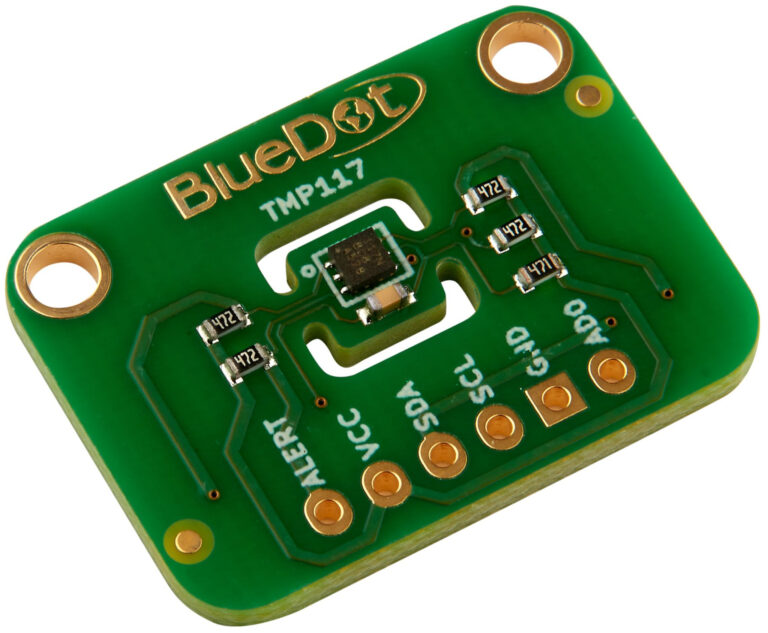
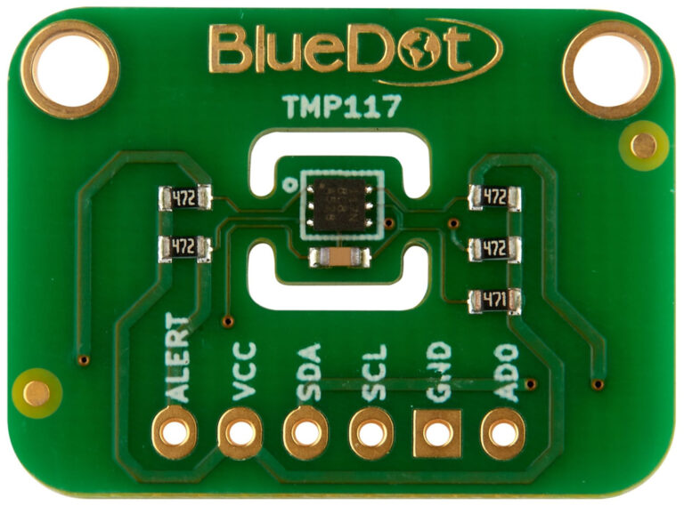
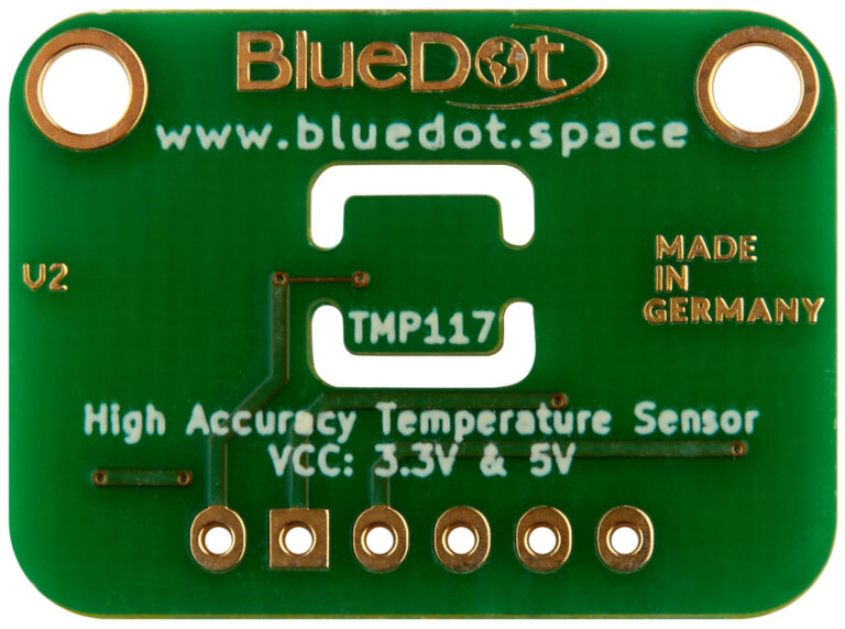
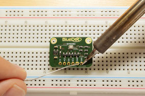
The TMP117NAIDRVR is a high-precision temperature sensor from Texas Instruments, capable of measuring temperatures with a typical accuracy of ±0.1°C across the range of -40°C and 100°C with no calibration.
Now let’s get started with the BlueDot TMP117 and take our first steps with this temperature sensor.
Description
Here are the board’s main features:
- High Accuracy and High Resolution. Typical measurement accuracy of ±0.1°C across the range of -40°C and 100°C. The TMP117 also provides a 16-bit temperature result with a resolution of 0.0078°C.
- Wide Range Supply Voltage. The sensor operates from 1.8 V and 5.5 V at VCC, dispensing the need for voltage regulation.
- Low Power Consumption. It has a very low power consumption, typically 3.5 µA, which minimizes the impact of self-heating.
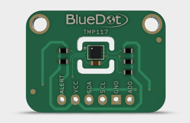
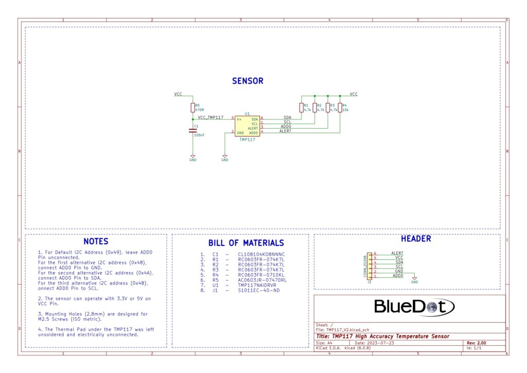
- I²C Communication. The sensor communicates through the I²C protocol using 0x49 as the default address. By connecting the AD0 Pin to either GND, SDA, or SDL the addresses 0x48, 0x4A, and 0x4B are also available.
This quick start guide on the BlueDot TMP117 will show you how to take the first steps with this temperature sensor board.
Connecting via I²C
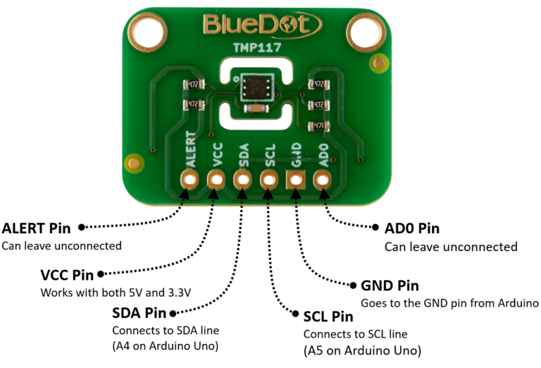
Connecting the TMP117 to the I²C bus is very easy. The first step is to connect the board to the power supply.
- VCC Pin. Connect the VCC pin from the board to either 5V or 3.3V output from your Arduino.
- GND Pin. Connect the GND pin from the board to the GND from the Arduino.
Great! Now we need to connect the sensor to the I²C bus. The I²C communication uses two wires. The clock signal is generated by the Arduino and transferred to the sensor through the SCL line. The Arduino can send commands to the sensor using the SDA line. Just as well, all data from the sensor goes back to the Arduino through the SDA line. Because of that, the SDA line is bidirectional.
- SDA Pin. Connect the SDA pin from the board to the SDA line on the Arduino. This corresponds to the pin A4 on the Arduino Uno.
- SCL Pin. Connect the SCL pin from the board to the SCL line on your Arduino. This corresponds to the pin A5 on the Arduino Uno.
- ALERT. You can leave it unconnected.
- AD0. You can leave it unconnected.
Installing Arduino Library
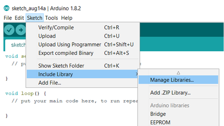
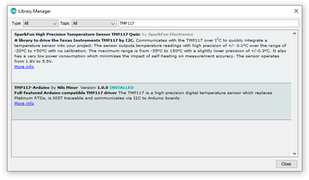
Although there is currently no Arduino Library from BlueDot available for this sensor, you can use the great library written by Nils Minor to connect to the TMP117. You can download and install the library directly from the Arduino IDE. Just open the Arduino IDE and go to Sketch > Include Library > Manage Libraries… and search for the TMP117 on the Library Manager. You can find this library under the name TMP117-Arduino.
Upload Example-Sketch
After installing the library we can open an example sketch. Just go to File > Examples > TMP117-Arduino and open the sketch simple_test.
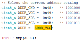
One minor change is needed to run the sketch. Just change the value of ADDR to ADDR_VCC. Note that the baud rate is set to 115200 per default.
This is the sensor output with the Timestamp from the Arduino IDE turned on

3D Model
A 3D model of the BlueDot TMP117 board is available as a STEP file (click here to download). A STEP file is a CAD file format widely used for exchanging CAD files between companies and can be easily read by most (if not all) CAD software applications.
You can also view 3D models online without installing any software on your computer. The images below were taken using Autodesk Viewer, an online, free-to-use tool from Autodesk. It does require registration at Autodesk, but it is worth it!

